Analogic VUmeter
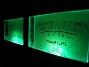
For my stereo tube amplifier I wanted to add two VU-meters to get an idea of the output power, looking on the net I found only “active” suggestions, that is a milliammeter driven by transistors or even by operational amplifiers.
The VU-meters indicate the gain of the amplifier in dB which is a unit of measurement with a logarithmic trend to better follow the acoustic perception of the human ear. My desire was to find a simple way to condition the linear signal, output from the amplifier, in logarithmic. Looking better I found a wiring diagram that I define brilliant and you can see at this link http://elizeueletrotecnico.blogspot.com/2021/01/circuito-esquema-vu-meter-analogico.html
As you can see in the image on the side there is only a diag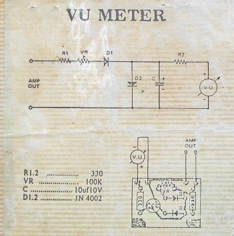 ram with components list. What I did not understand was the direction of the diode D2, for me it was wrong. Suddenly observing the circuit better, I realized that the diode D2 provides a voltage with a logarithmic trend to the instrument. With this principle I designed a circuit that can be used with amplifiers up to 100 W.
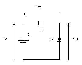
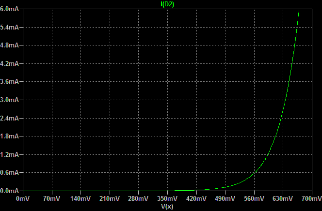
We have seen that the operating principle is the logarithmic voltage behavior of the diode, caused by the variation of the current flowing through it, between 0.35 V and 0.66 V. In the drawing we simplify by indicating the input voltage as V and the exit voltage as V d. The voltage V d is linked by logarithmic law to the current I d which flows through the diode :
Vd = η*VT*logn (Id/Is)
Where:
V d is the voltage across the diode
I d is the current running through the diode
I s is the inverse saturation current which is worth about 10-12 A
η is equal to 1 in the conduction zone or 2 in the case of very large current values
V T thermal voltage which is approximately 25 mV at 300 K
Without bothering algebra and non-linear networks, let’s try my circuit in LTSpice:
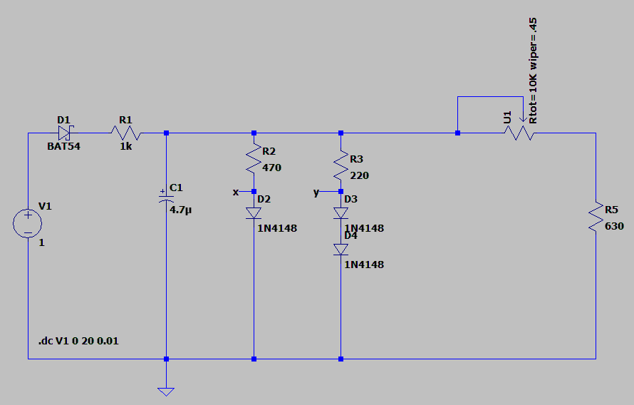
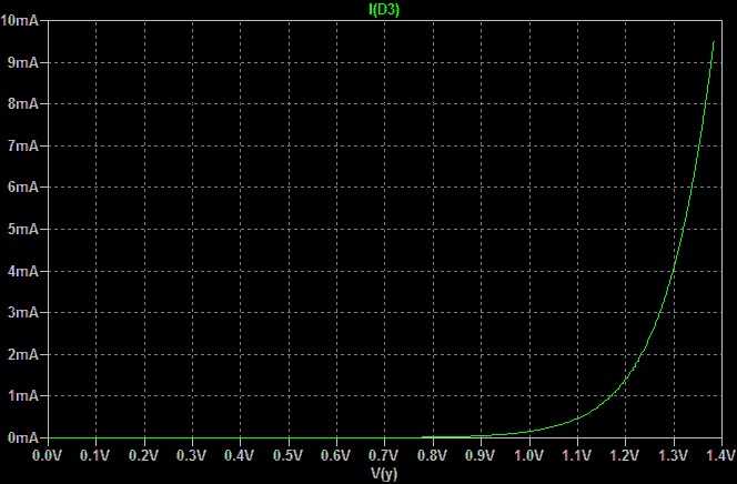
The milliammeter I used is the classic 630 Ω with 0.530 μA at full scale, so the maximum value to apply to it is about 0.334 V. The first part of the circuit reduces the voltage level, from wires connected to speakers, and makes the envelope of the signal to the following resistors and diodes network. Diode BAT54 is a Schottky effect diode with low threshold voltage (just over 0.15 V), high switching speed and above all a reverse voltage of at least 100 V. Now, the current flowing in the first 1N4148 diode causes a voltage drop that follows the law indicated above (logarithmic). However, the signal becomes linear for voltages over 0.66 V so the third part of the circuit performs the same operation as the second part but with two diodes in series up to 1.32 V. After this value, the signal remains linear. At this point a variable resistor brings the signal, made quite logarithmic in the power excursion, to the milliammeter. With this circuit we can have a VU-meter that works up to 25 V of output from the amplifier (into 8 Ohms) which means an electrical power of about 100 W.
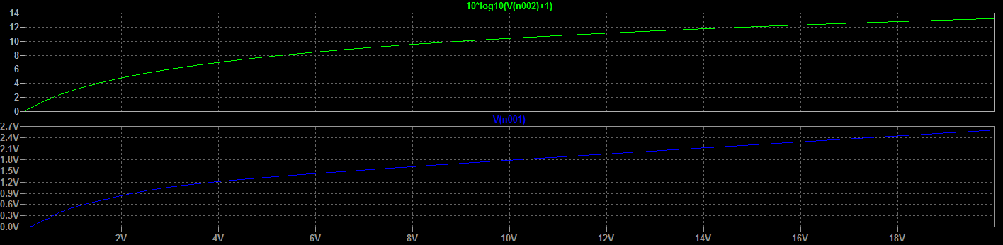
My stereo tube amplifier provides about 3 W per channel on 8 Ω load, that means a voltage of about 4.9 V applied to the speaker (W = V 2 / R) and after the diode D1 we have an effective voltage vaule of 4.9*1.414=6.92 VRMS. The diagram below shows the DC sweep between 0 and 20 V applied to the circuit. Important! the current flowing in R2 is about 17 mA therefore the electrical power that must dissipate is 0.017 * 0.017 * 1000 = 0.289 W so the resistor must be at least 1/2 W or more if the circuit is used with an amplifier that supplies 100 W.
In the following diagram we have a blu trace that is the voltage before the variable resistor U1 , while the green trace is the theoretical logarithmic curve where v(n002) is voltage of V1. I did not need the maximum accuracy in the measurement, it was enough that it was indicative, so I can consider myself satisfied with the result.
The charge time T of capacitor is dictated by the pair R2 and C1 of 1 kΩ and 4.7 μF respectively:
T= R2 x C1 = 1000 * 4.7 x 10 -6 = 4.7 milliseconds
This T is approximately 4.6 times the time costant so tau is about 1 millisecond that is small enough to don’t affect the time delay of the indicator instrument which is typically 300 milliseconds.
Correct calibration is not laborious but requires the use of a 1000 Hz sinusoidal signal generator and an oscilloscope. The volume is adjusted until it reaches 4.9 V (for 3 W output) and then the variable resistor is adjusted until the instrument index reaches 0 dB.
The LTspice file can be downloaded here https://automatico.freevar.com/dump/vumeter.asc
Potentiometer model with installation instructions in LTSpice are here https://automatico.freevar.com/dump/potentiometer.zip
![]()
