Noise Generator Model
Our aim is to create an oscillator that provides an output voltage with a random trend and from this create random pulses in turn to simulate the operation of a Geiger-Müller ionization chamber tube. For this we will use a Colpitts oscillator which will get trapped in the noisy phase before the regular periodic oscillation and a voltage comparator to filter the voltage levels below a given value.
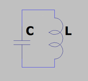
Resonance in an LC circuit occurs when the oscillation frequency has the greatest amplitude and this is when the inductive impedance and capacitive impedance have the same value.
\[ Z=R+(X_{L}-X_{C}) \]
We know that \[ X_{L}=\omega L \] and \[ X_{C}=\frac{1}{\omega C} \]
Because \[ X_{L}=X_{C} \] we have \[ \omega L=\frac{1}{\omega C} \] so if we specify in ω we obtain
\[ \omega=\frac{1}{\sqrt{LC}} \]
We also know that \[ \omega=2\pi f \] therefore the resonant frequency holds
\[ f=\frac{1}{2\pi\sqrt{LC}} \]
All this in the ideal case with R equals 0.
Now if we divide C into two capacities we have the Colpitts oscillator:

The value of C is given by the series of the two capacities:
\[ C=\frac{C_{1}*C_{2}}{C_{1}+C_{2}} \]
During the oscillation in the real circuit there is a loss of energy due to the resistance R. An active device is needed to compensate for this lost energy and thus sustain the oscillation.
The oscillation in the Colpitts circuit depends on the phase shift of the signal as well described in the Barkhausen criterion for oscillators. According to the Barkhausen criterion, the gain of the circuit should be slightly greater than unity and the phase shift of the signal should be 2π radians or 0 radians. Therefore, during this case, to output oscillation, the circuit must provide a phase shift of 0 radians (or 2π radians). The LC circuit contributes a π radians phase shift and a further π radians phase shift is given by the active circuit.
The trigger of the oscillation is given by the voltage difference present at the ends of the two capacitors of different capacities C1 and C2. Determining the feedback voltage is a crucial part of the circuit because a low feedback voltage value would not trigger oscillation while a large amount of feedback voltage would destroy the output sine wave and induce distortion.
Let’s now see the active part of the oscillator circuit:
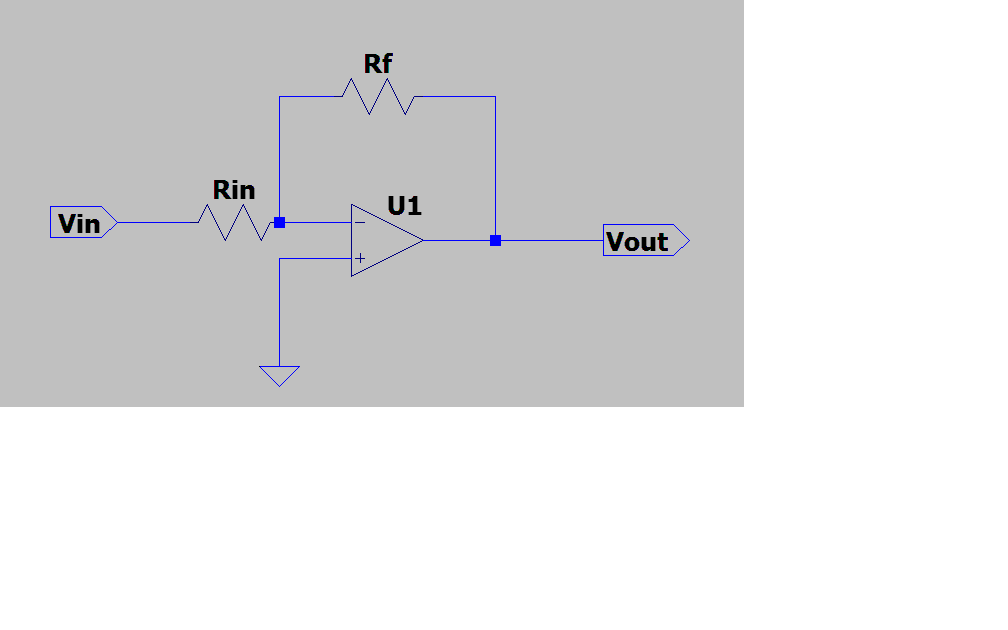
To build our oscillator we will use an operational amplifier circuit in inverting configuration where the output voltage is related to the following law:
\[ V_{out}=V_{in}\frac{R_{f}}{R_{in}} \]
Let’s now see at the component values for a sinusoidal oscillation. Let’s assume that the capacitance of C1 is 2.2 μF and the capacitance of C2 is 1 μF, furthermore that the inductance L is worth 100 μH. Let’s calculate the series between the two capacities:
\[ C=\frac{C_{1}*C_{2}}{C_{1}+C_{2}}=\frac{2.2*1}{2.2+1}\mu F\approx0.6785\mu F \]
With these values we therefore have a fundamental resonance frequency of:
\[ f_{0}=\frac{1}{2\pi\sqrt{LC}}=\frac{1}{2\pi\sqrt{100*10^{-6}H*0.6785*10^{-6}F}}\approx19195Hz \]
The β value indicates how much signal returns to the LC group, its inverse indicates how much the signal must be amplified to have a unity gain according to the Barkhausen criterion:
\[ \beta=\frac{X_{C1}}{X_{C1}+X_{L}} \]
where
\[ X_{C}=\frac{1}{2\pi*f_{0}*C}\approx\frac{1}{2\pi*19195Hz*2.2*10^{-6}F}\approx3.77\Omega \]
\[ X_{L}=2\pi*f_{0}*L\approx 2\pi*19195Hz*100*10^{-6}H\approx12.06\Omega \]
So
\[ \beta=\frac{3.77}{3.77+12.06}\approx0.238 \]
From the β value we can simply calculate the gain of the active part of the oscillator
\[ A_{V}=\frac{1}{\beta}=\frac{R_{f}}{R_{in}}\approx4.2 \]
\[ \frac{R_{f}}{R_{in}}=\frac{42k\Omega}{10k\Omega} \]
So we have L1=100μH, C1 = 2.2 μF, C2 = 1 μF, R1 = 10kΩ, R2 = 42kΩ to get a sinusoidal oscillation frequency of 19.195 Hz.
Now, to have spurious oscillations it is necessary to alter the value of 1/β and bring it to 10.
With this new AV value we have a 10 times gain and finally get the two new values R1 = 10kΩ, R2 = 100kΩ.
So our circuit could be composed as follows:
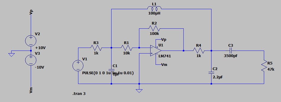
In the image above we finally have the Colpitts oscillator circuit based on an operational amplifier. The operational amplifier is in inverting configuration. Resistors R1 and R2 are sized to provide the required output from the operational amplifier. The inverting operational amplifier is connected in parallel to the inductance L and to the capacitors C1 and C2 in series each other. Then the operational amplifier input is connected to the oscillating circuit feedback. With these parameters the circuit oscillates at a little less than 20 kHz.
During start-up, the operational amplifier amplifies the noise signal given by the different charge of the two capacitors. A pulse generator via resistor R3 sends a 1 Volt signal 100 times per second to trigger the oscillation that gets trapped in the noisy phase.
The result is in the following diagram:
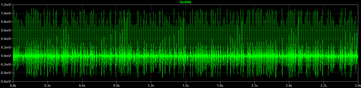
![]()
